

Features
- Oval, octagonal or special profiles.
- “Ring Joints”, according to ASME and API standards, are normally used in the petrochemical industry and in refineries.
- They offer great safety in demanding application conditions both in “piping” product lines and in other types of equipment.

Profiles and values
Ring Joints or R.T.J. are usually manufactured from metallic materials, which generally offer high mechanical strength values. This causes the requirements for dimensional accuracy and surface finish to be very high, affecting both the joint and the flange seat box.
The surface finish of the joint depends substantially on the Brinell hardness of the joint material. In this regard, we have found that the following ratio Rz (mm) 300/HB, which provides a good guideline on the necessary finish.

Features and details
It is usual to make a distinction between different types of ring joints, which consequently have different calculation methods:

Ring Joints with rounded (oval) seating faces
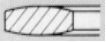
 Oval gasket, R‐OV profile, with rounded seating faces, whose manufacturing radius is half the thickness of the gasket.
The deformation process of the gasket during tightening is similar to that of the convex octagonal gasket.
In both types, the projection of the surface contact area of the gasket bD comes from the contact inclination angle (usually 23º). Thus, the contact area between the gasket and the flange is variable, depending on the local tightening force supplied , the modulus ED and the number of contact faces n (2 in these cases).
The relationship between these variables can be expressed as:

It is important to note in the above relationship that the surface stress increases or decreases depending on the tightening load provided by the bolts, affecting the contact surface bD existing at that time.
Ring Joints with flat (octagonal) seating faces

This is the case of the classic octagonal joints, Profile R‐OCT, whose contact surfaces are completely flat. The contact surface is summarised in the relation bD = b1 + b2
Obviously, the surface stress increases or decreases depending on the tightening load provided by the bolts.
The calculations made from the DIN 2505 standard with the joint parameters k0 and k1, which represent a fictitious width, do not sufficiently address the problem of the complicated conditions of the “Ring Joint” joints with rounded contact faces.
Surface pressure
The table of minimum stresses min (joint closure) and max. maximum (breaking limit) for “Ring-Joint” joints is presented below.

TECHNICAL DATA
ASME B 16.20
For ANSI/ASME B 16.5 and
ASME B 16.47 Series A flanges
dm: Average diameter (mm)
b: Width (mm)
h: Oval profile height (mm)
h1: Octagonal profile height (mm)


TECHNICAL DATA
ASME B 16.20
For ANSI/ASME B 16.5 and
ASME B 16.47 Series A flanges
dm: Mean diameter (mm)
b: Width (mm)
h: Oval profile height (mm)
h1: Octagonal profile height (mm)


TECHNICAL DATA
ASME B 16.20
For ANSI/ASME B 16.20 flanges
Profile (RX)


TECHNICAL DATA
ASME B 16.20
For ANSI/ASME B 16.20 flanges
Profile (BX)

